- p. 21
- The original DEC/Intel/Xerox Ethernet (at 10Mb/sec: there was
an experimental version at 3Mb/sec) is now known as ``thick''
Ethernet, and was carried on a bulky co-axial cable, with quite severe
restrictions on bend radius etc., and with precise specifications for tapping a
station into the cable. This had a maximum length of 500 metres, and a
delicate means of connecting machines to it -- the so-called ``vampire
tap''.
This is now known as 10base5 Ethernet, the ``10'' standing for the
10Mbps transmission rate of frames and the ``5'' for the maximum length.
A newer version, known as ``thin'' Ethernet or ``cheapernet'', was carried
on much thinner and more flexible co-axial
cable, with relatively simple BNC connectors. There was a smaller
maximum length (185 metres) but this proved much more suitable for cabling
offices etc., particularly in existing buildings. This is known as 10base217 Ethernet. More
recently, Ethernet-format signals can be carried on
category 5 UTP18, when it is known as 10baseT (limited to 100m to the hub) or on optical fibre 10baseF.
Higher-speed Ethernet variants are possible on these last two media, and
100Mbps Ethernets (100baseT over twisted pair, limited to 100m, or
100baseFX over optical fibres, limited to up to 20km, depending on
the precise optical nature) are available, and
some manufacturers are offering 1000Mbps products19 such as 1000baseT, limited to
100m20, or 1000baseSX (500m) and 1000baseLX (2km or even 15km -- see http://www.premisesnetworks.com/read/nl20011022/469878) over
fibre. On 13 June 2002, IEEE ratified 802.3ae, 10 Gigabit Ethernet,
which allows 300m over multimode fibres and 40km over single-mode fibres.
- p. 22
- Ethernet ``hardware addresses'' are assigned by the
manufacturer of the Ethernet chip or card, from a range that the
manufacturer is allocated by the IEEE21 -- see RFC 1700 for some such
allocations, and ftp://ftp.isi.edu/in-notes/iana/assignments/ethernet-numbers for the
most recent list. Hence the address can tell one something about
the nature of the machine. These will stay with the card or chip for life.
So, if a machine is transferred from one University to another, it will
keep its Ethernet address, but acquire a new IP address from the range of
the new owners. One can think of the Ethernet address as being like the
chassis serial number on a car, which is the same even if the car transfers
countries (or, in France, departments) and has to be re-registered.
- p. 22
- Note that the RFC 894 encapsulation has no ``length'' field. The
length of the Ethernet frame is deducible from the frame (else the hardware
would not know which four bytes were the trailer), but of course this will
include any padding to the minimum length of 60 bytes (+ trailer). Since IP
has its own length field (see page 36), this is not a problem with RFC 894
encapsulation, but the designers of IEEE 802.2/802.322 wanted to be able to carry
data that was not self-describing, so needed a length field.
- p. 22
- The 1500 bytes maximum payload was a necessary
restriction on 10base5 and 10base2, in order to prevent one site
hogging the shared medium for an excessive time. With the move to
non-shared media (baseT, baseF), this is not such a problem. However,
the frame size has been kept23 at 1500 to allow bridging at the Ethernet
level between different media/speeds: it is common for a 10baseT hub
to have a 100baseT outlet to the main network, for example. Some
1000base manufacturers allow for larger frames: Alteon allows ``jumbo
frames'' of 9000 bytes, for example. However, since Ethernet has no
provision for fragmentation24, these cannot be bridged at the Ethernet level to
other media/speeds, or even other vendors that don't support this
option. Interoperability is a great enemy of change.
- p. 22
- (This note is only for those of a mathematical inclination.)
The sort of CRC used for Ethernets is defined as follows.
Choose a Boolean polynomial
 (i.e. a polynomial whose coefficients are
integers modulo 2, i.e. 0 and 1) of degree 32 such that:
(i.e. a polynomial whose coefficients are
integers modulo 2, i.e. 0 and 1) of degree 32 such that:
- the polynomial is irreducible25,
i.e. has no proper factors;
- the polynomial is primitive, i.e. the powers of
 , from
  to
to
 modulo are all different.
Such a polynomial is
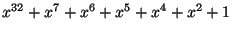 . Regard the whole
message as a polynomial in , whose coefficients are the bits in the
message, and the CRC is the remainder when this is divided by .
. Regard the whole
message as a polynomial in , whose coefficients are the bits in the
message, and the CRC is the remainder when this is divided by .
In practice, this is easy to compute in hardware: build a 32-bit linear
feedback shift register corresponding to . In the case above, this would
feed out of the top of the register back (via exclusive-or) into bits 7, 6,
5, 4, 2 and 0. Then feeding the entire message through this register leaves
the remainder in the shift register. The use of a shift register with
feedback explains the word ``cyclic'' in ``Cyclic Redundancy Check''.
- PPP uses a CRC of the same nature as Ethernet, except that it is,
by default, based on a polynomial of degree 16. The polynomial in question is
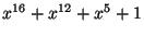 -- see RFC 1662 for details and a fast software
implementation for 16 or 32 bits. It is possible for PPP links to
negotiate the use of a 32-bit CRC.
-- see RFC 1662 for details and a fast software
implementation for 16 or 32 bits. It is possible for PPP links to
negotiate the use of a 32-bit CRC.
This sort of CRC is efficient, in the sense that it will detect all one-bit
errors, nearly all single bursts of errors and most more complex errors. It
is relatively expensive to compute in software, but easy to compute in
hardware. See the discussion on page 36 for a comparison with the IP
algorithm.
- Section 2.3
- This is now completely obsolete.
- Section 2.4
- SLIP is fading away now in the presence of PPP, and the
statement at the bottom of page 27 is now false. RFC 1812 requires
that routers support PPP on all point-to-point links. Nearly all PPP
implementations support header compression (the same algorithm as CSLIP), and
RFC 1812 mandates it for links up to 19200 baud. Header compression is
described in RFCs 2507-9, 3095, 3096 and 3544.
- p. 26
- RFC 1548 has been obsoleted by RFC 1661, as updated by
RFC 2153.
- p.31, l. 8
- It is not the MTU that we are reducing to 256 bytes,
but the data length. If the data length is to be 256, we have to quote
an MTU of 296, since TCP will subtract 40 bytes of fixed TCP and IP headers
(see page 237) to compute its Maximum Segment Size. However, the
calculations assume that the headers are compressed to five bytes, so use
261 as a packet length. Similarly, the figure of 261ms quoted is based
on a SLIP packet of 256 bytes (which would occur if we quoted an MTU of
291, since 291-40+5=256). The correct figure is 272ms, which halves to
136ms. The general conclusion is unaltered.
Header compression, while very valuable (note that a compressed
256+header
byte packet has 1.9% header overload, whereas an uncompressed 256+header
byte packet has 13.5% overhead), is a complete violation of the layering
principle, since the CSLIP/PPP implementation has to look up the protocol
stack to the IP and TCP layers to perform the compression. We should note
that only TCP, which is connection-oriented, benefits from this
compression: NFS over UDP, which sends many packets to and from the file
server, does not, since although there's a logical connection, there isn't
one at the UDP level, since UDP is not connection-oriented.
- p. 31
- At today's more common 33,600 baud, the 272ms reduces to 78ms,
which is a very acceptable delay. It would be reasonable to consider
increasing the maximum data length from 256 bytes to 512 (the MTU from 296
to 552), which would increase the delay to 154ms, but make the overhead
0.9%. This is not a great gain: the greatest gain comes from reducing the
number of packets required to carry a message, reducing CPU load and
overhead elsewhere in the system: on a non-compressed link following the
PPP link, the TCP and IP header overhead would drop from 14% to 7%.
In fact, the greatest gain would come in reliability due to the decrease in
fragmentation (see the notes to page 151 and [6]). Consider an
NFS write command,
of 8192 bytes (the usual UNIX block size) plus, say, 60 bytes of UDP and
NFS header information from a remote machine. With an MTU of 296, we can
fit 276 bytes of UDP information into a fragment, so this takes
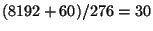 fragments, whereas with an MTU of 552, this takes
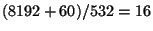 fragments. If we assume a 1% loss rate on the wider
Internet, then an IP packet split into 30 fragments has a 26% chance of
being lost (i.e. one fragment is lost, but this loses the whole IP packet),
whereas with 16 fragments there is only a 15% chance of it being lost. If
we assume a 5% fragment loss rate, then a 30-fragment packet has a loss
probability of 79%, requiring on average 4.66 transmissions for success,
whereas a 16-fragment packet has a 56% loss rate, requiring 2.27
transmissions on average. At a 10% fragment loss rate (not impossible in
practice) the average number of transmissions is 23.59 for 30 fragments and
5.40 for 16.
fragments. If we assume a 1% loss rate on the wider
Internet, then an IP packet split into 30 fragments has a 26% chance of
being lost (i.e. one fragment is lost, but this loses the whole IP packet),
whereas with 16 fragments there is only a 15% chance of it being lost. If
we assume a 5% fragment loss rate, then a 30-fragment packet has a loss
probability of 79%, requiring on average 4.66 transmissions for success,
whereas a 16-fragment packet has a 56% loss rate, requiring 2.27
transmissions on average. At a 10% fragment loss rate (not impossible in
practice) the average number of transmissions is 23.59 for 30 fragments and
5.40 for 16.
In practice, we would probably increase the MTU to 576, since this is the
default value for Internet MTUs, and may well prevent fragmentation of
incoming TCP packets at the PPP interface. This would make the delay 161ms,
or 162ms if we allow for the fact that we're probably running PPP rather
than SLIP, so should allow for 3 bytes of PPP framing.