| Read more about the Team Green vehicles -
click to
expand each section Teamgreen
1 vehicle - 1996
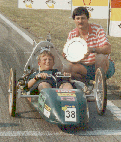
The first year that Team Green has entered the Shell International Mileage Marathon / Eco-Marathon event was in 1996, when the major effort was given towards designing and making a 4-stroke engine. It combined a number of features that would help the fuel efficiency, such as fuel injection, a long stroke to bore ratio, twin spark plugs etc. Following the manufacture of the engine little time was available for the construction of a competitive vehicle, so a very simple flat bed chassis was made. This enabled an entry to be made at the event, which unusually was held at Mallory Park circuit. The chassis was made from rohacell covered in glass fibre, stiffened by a mast from a sail board. The front wheels were attached to a solid axle that pivotted to allow front wheel steering. The wheels were standard 20 inch cycle wheels and the tyres were low hysteresis Michelin crossply slicks designed for the event.
Teamgreen
2 vehicle - 1997 - 1999
In order to achieve best miles per gallon figures it is important that very little energy is necessary to propel the vehicle at the required speed. This can be achieved by keeping the mass of the vehicle and driver to a minimum, and the aerodynamic drag force to a minimum. (In other words having a lightweight car with a sleek body shape, which moves through the air easily). The car body shape was formed from plaster which was supported by a wooden framework and wire mesh. Using GRP (glass and carbon fibre reinforced plastic) to cover this male shape, a thin smooth body was made up in 2 halves. The lower half was stiffened up with foam and more GRP to make a monocoque chassis capable of mounting the engine and transmission etc and of course supporting the driver!
Tests in a Wind Tunnel at the University of Bath indicated that the car has an impressive 0.12 drag coefficient. This together with the minimal cross sectional area of the car means that it only requires approximately only one tenth of the energy of an average passenger car to overcome aerodynamic drag.  The driver lays on their back in the vehicle with their feet forward; this allows the low shape of the vehicle.
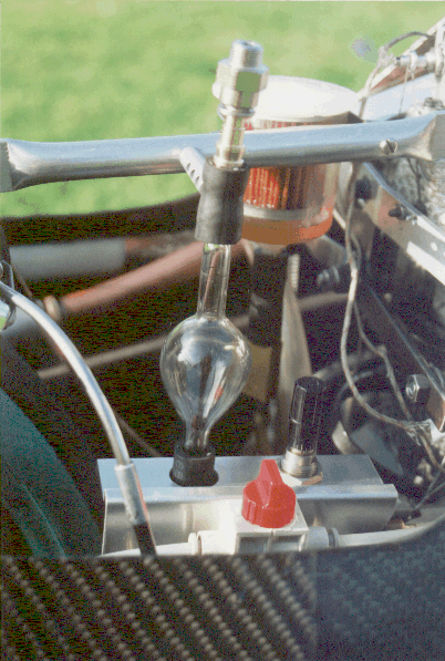
The engine has a 34 cc single cylinder and it operates with a normal 4-stroke cycle. It uses standard unleaded petrol supplied by Shell. It has 2 spark plugs, variable inlet valve timing and fuel injection. The ignition and fuel injection are controlled by an Engine Management system provided by GEMS (General Engine Management Systems Ltd) . This is able to keep the engine working most efficiently. The drive from the engine is taken via a centrifugal clutch and chain drive system to the rear wheel. This vehicle has been sold to the University of Bath, and was used as a University diesel vehicle for a few years. 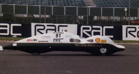 Teamgreen
3 vehicle - 2000 - 2005
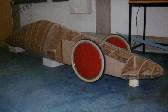
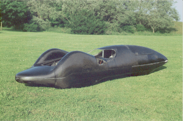
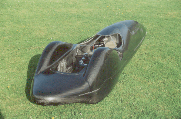
During the year leading up to the 2000 competition a new vehicle was developed. The following description explains briefly how the vehicle was manufactured. Construction of the Buck Following a few weeks spent designing the shape of the new vehicle on paper drawings, considerable time was devoted to making a full scale model of the new shaped design. This model was carved from blue styrofoam (building insulation material) to give a buck around which a fibre glass mould could be formed. The buck also enabled various checks to be made on the feasibility of the design, for example whether the driver would fit into the shape and what the visibility would be like. The surface of the buck was coated in filler and matt emulsion and rubbed down to achieve a good finish. After this 3 layers of sealant were applied to seal the porous surface and to give a shiny surface from which the mould could be removed easily.
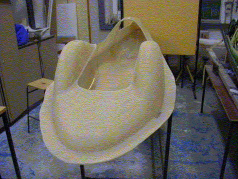
Making the Mould Several coats of wax and PVA were applied as mould release agents before laying up glass fibre over the buck. The glass fibre was applied to the buck in 2 halves (top and bottom) each meeting at a flange which allowed the mould to split and be released from the buck. The 2 halves were persuaded to release from the buck with the assistance of air line pressure. Before separating, the flanges were drilled so that they could be fixed together with screws. This enabled easy alignment of the 2 halves when used to lay up the final vehicle shape. Two apertures have been cut from the top half of the mould to allow access into the final vehicle for the driver and the engine/rear wheel assembly. These can be used to gain access to lay up the carbon fibre/epoxy resin within the assembled mould.
Laminating the New Shell After applying release agent to the mould, the vehicle outer shell has been laminated using carbon fibre fabric and epoxy resin.
Having removed the shell from the mould, reinforcement, using Rohacell has been added to stiffen the shell, making it into a structure strong enough to carry the driver and engine. This monocoque construction is also strong enough to attach the steering and suspension components etc. The Carbon Fibre fabric and epoxy resin for the vehicle has been generously donated by Polymeric Composites of Clevedon. Amber Composites of Nottingham have donated additional epoxy resin. Roehm Ltd of Milton Keynes has
donated a sheet of Rohacell rigid foam which will be used for
reinforcement.
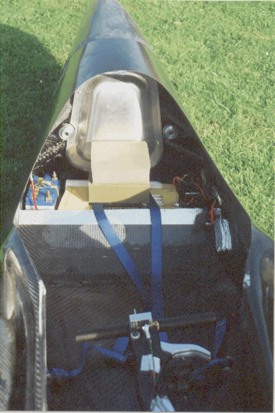
In view of the amount of work necessary to make a new vehicle, it was decided to make use of a number of components from the previous vehicle - engine, transmission, wheels, electics etc. This included the purpose made harness from Total Restraint Systems, Salisbury.
Because of the minimal space within the engine compartment and the continual search for weight reduction, the fuel system was overhauled. A new smaller reservoir was made by Mike Lock - Glassblower at the University of Bath, and SMC Pneumatics (UK) Ltd of Milton Keynes supplied a number of pneumatic fittings and components for the fuel pressurising system.
The wheel bearings were renewed by BSL of Bath, and polycarbonate sheet was provided by AMARI Plastics, Weybridge for the windscreen.
Teamgreen
4 vehicle - 2006 - date
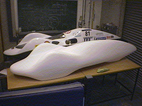
During the year 2005 is was becomoing clear that the Teamgreen 3 vehicle was coming to the end of its competitive life. Even though it had been used to clam the British Record at the Scottish event with 6603mpg it was felt that this was as good as the vehicle was going to get given the method of construction of the main bodywork. The carbon composite has not been manufactured using the best techniques and has unfortunately resulted in a heavy vehicle with excess resin locked in. The total weight of 42kg is somewhat heavier than other more competitive vehicles and so a decision was made following the 2004 events to design and build a new one. The process of designing and building has taken 2 years and has involved the invaluable help and assistance of Steve Thomas at C12 Composites. 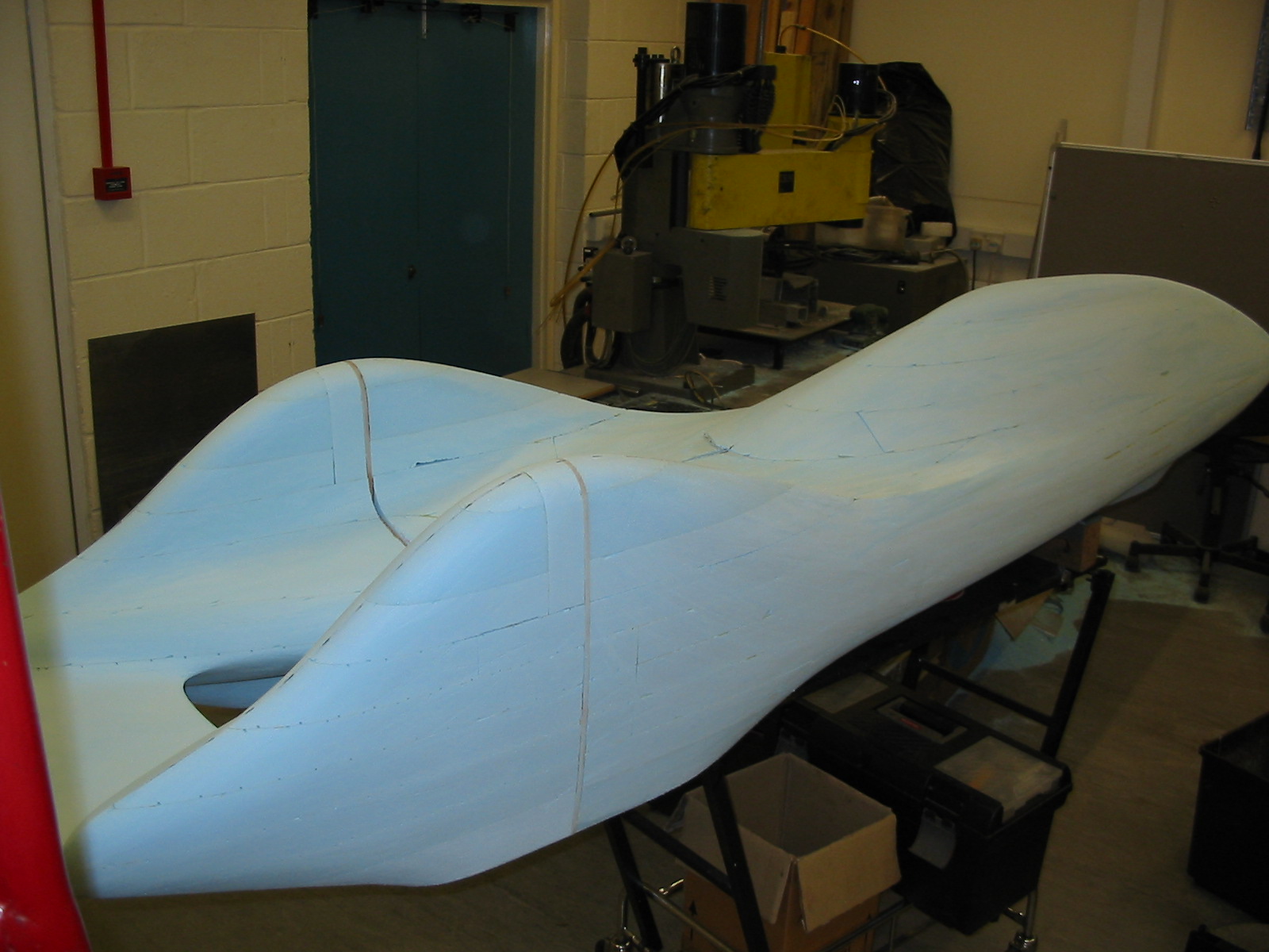 Frances had booked a flight with
BMI before the security
problems with flying arose, but fortunately her flight on Friday was
not affected much and she arrived just after lunch, allowing us to get
some early practice with the steering around the
track. We had adjusted the steering to allow for the tighter bends and
we were pleased that we were able to adjust it back towards the setting
for Rockingham allowing greater mechanical advantage for
Frances. She was very happy with the steering and we were then able to
concentrate on developing a suitable driving strategy for the
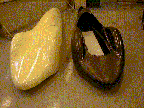
new vehicle and trying to improve the performance. The picture above
shows the blue styrofoam model of the vehicle shape. The
aerodynamics of the shape have developed to minimise the frontal area
along the vehicle as much as possible. The use of rear wheel steering
has further enabled this reduction especially around the front wheels. 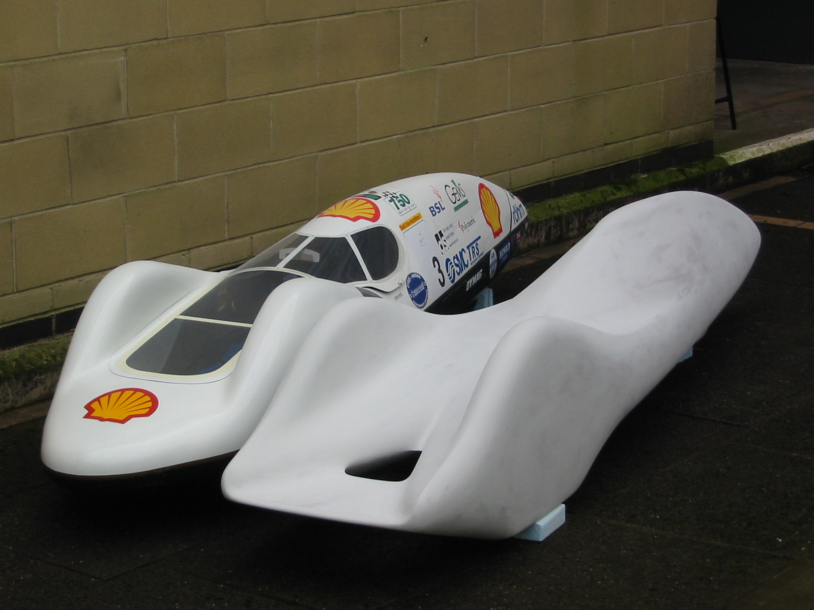 After the foam shape was modelled, the shape was covered in glass fibre and car body filler before being rubbed down to the required final shape and finish. The picture above shows the comparison between the Teamgreen 3 and Teamgreen4 shapes. 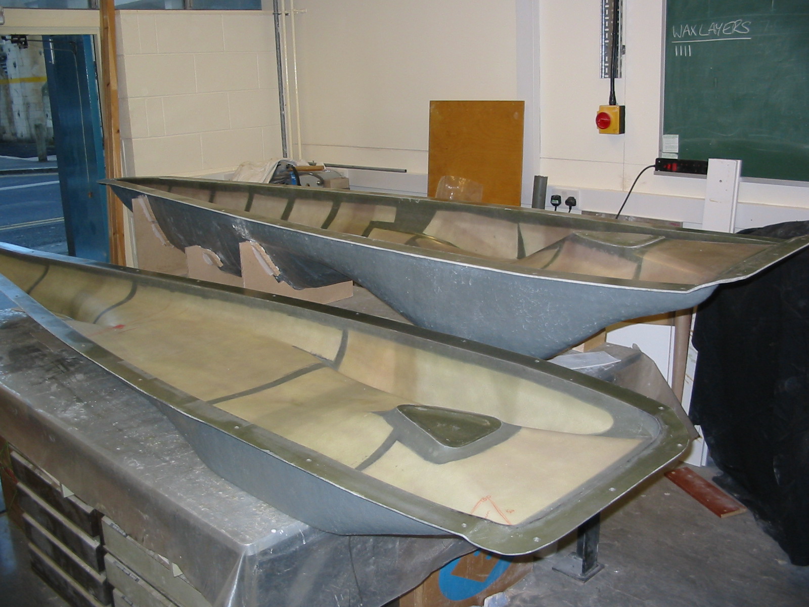 After the full sized model was completed, a glass fibre mould was created in 2 halves to enable the carbon fibre mouldings to be laid up. The laying up was carried out by Steve Thomas using vacuum bagging techniques to minimise the weight of epoxy resin present in the final moulding. 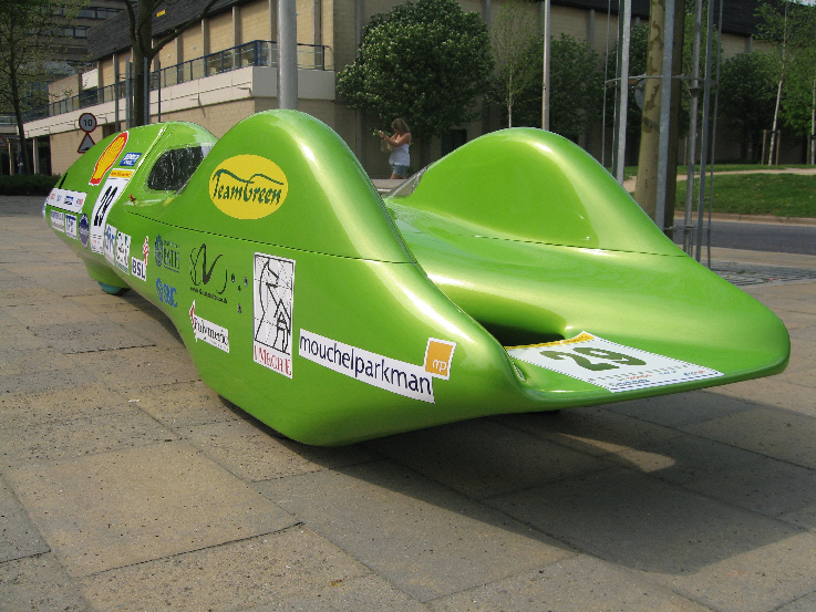 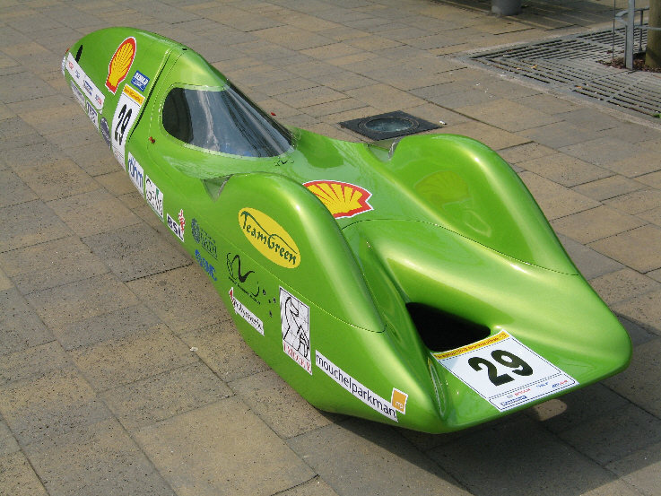 |